Get an Instant Quote
Choose a service
- No: This part does not have any export control.
-
Yes: This part is subject to export control regulations such as ITAR, EAR, or
otherwise considered Controlled Unclassified Information (CUI).
- Momentum Optics will only produce these parts with suppliers that have successfully gone through the appropriate registration process.
- Only US Persons will have access to sensitive information regarding this part.
- Your quoted price and lead time may be affected.
| Tier | Lead Time in Weeks |
|---|---|
| Economy | 6 weeks |
| Standard | 4 weeks |
| Accelerated | 2 weeks |
| Attribute | Standard | Precision | High Precision | |||
|---|---|---|---|---|---|---|
| + | - | + | - | + | - | |
| Edge Diameter | 0.1 | 0.1 | 0.05 | 0.05 | 0.025 | 0.025 |
| Center Thickness | 0.100 | 0.100 | 0.075 | 0.075 | 0.050 | 0.050 |
| Edge Thickness | 0.100 | 0.100 | 0.05 | 0.05 | 0.025 | 0.025 |
| Irregularity (RMS) | 0.790 | 0.790 | 0.474 | 0.474 | 0.316 | 0.316 |
| Irregularity (PV) | 2 | 2 | 1.5 | 1.5 | 1 | 1 |
| Radius of Curvature | 0.25 | 0.25 | 0.15 | 0.15 | 0.1 | 0.1 |
| Wedge (ETD) | 0.05 | 0.05 | 0.01 | 0.01 | 0.005 | 0.005 |
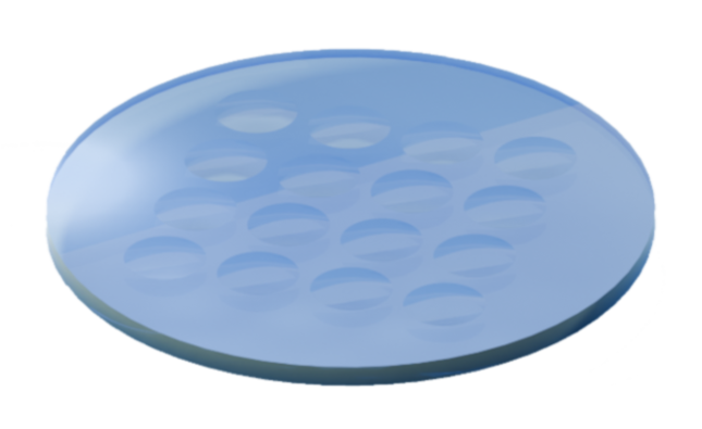
| Array Pitch | 0.050 | 0.050 | 0.025 | 0.025 | 0.010 | 0.010 |
| MFG | Name | In Stock | Refractive Index |
|---|---|---|---|
| Corning | 7980 Fused Silica, Standard Grade 0,F (Corning) | Yes | 1.4585 |
| Schott | N-BK7 (Schott) | Yes | 1.5168 |
| Schott | N-SF6 (Schott) | Yes | 1.80518 |
| Schott | N-SF11 (Schott) | Yes | 1.78472 |
| CDGM | JGS1 Fused Silica, Standard Grade (CDGM) | Yes | 1.4585 |
| CDGM | H-K9L (CDGM) | Yes | 1.5168 |
| CDGM | H-ZF13 (CDGM) | Yes | 1.78472 |
| CDGM | H-ZF7LA (CDGM) | Yes | 1.9037 |
Edge Diameter is the length from top to bottom if looking at the optic from the side. The Edge Diameter is the outer dimension of the part sometimes referred to as the "mechanical diameter" or "outside diameter."
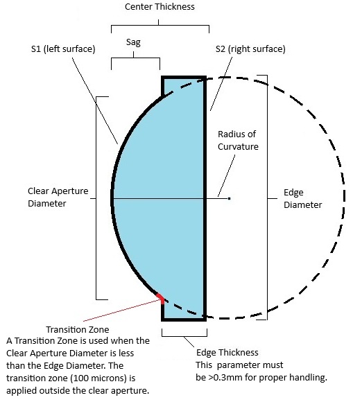
Center thickness is the depth at the centerpoint of the optic diameter.
Radius of Curvature is the radius of a circle that would end at the edge of the curved, outer surface of an optic.
Radius of Curvature Tolerance is the acceptable deviation from radius of curvature along the optic surface.
Irregularity (RMS - Root Mean Square) is the deviation of the surface from the ideal or prescribed surface. The irregularity is sometime referred to as the "Figure Error."
Irregularity (PV - Peak-to-Valley) is the deviation of the surface from the ideal or prescribed surface. The irregularity is sometime referred to as the "Figure Error."
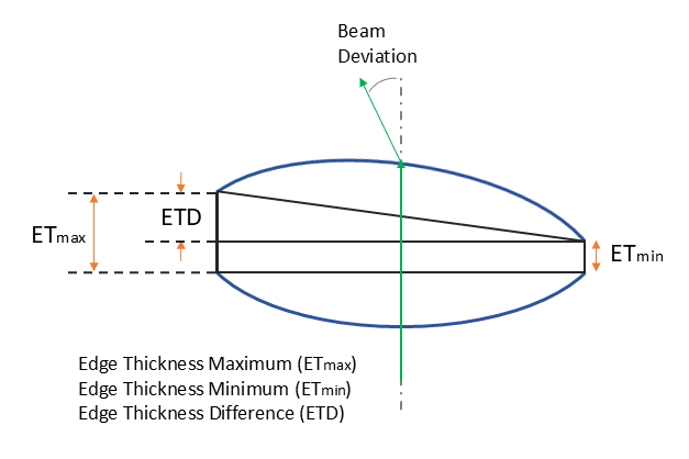
Wedge defines the lack of parallelism between two optical surfaces. It can be characterized as Total Indicator Runout (TIR) or Edge Thickness Difference (ETD). We measure ETD defined as the difference between the maximum and minimum edge thickness.
| Coating Name | Wavelength Range | Reflectance |
|---|---|---|
| AR | ||
| UV | 245 - 400 nm | Ravg < 0.5% |
| A | 400 - 700 nm | Ravg < 0.5% |
| AB | 400 - 1,000 nm | Ravg < 1.0% |
| B | 650 - 1,050 nm | Ravg < 0.5% |
| C | 1,050 - 1,700 nm | Ravg < 0.5% |
| D | 1,650 - 3,000 nm | Ravg < 1.0% |
| E1 | 2,000 - 5,000 nm | Ravg < 1.5% |
| E2 | 3,000 - 5,000 nm | Ravg < 0.5% |
| E3 | 4,500 - 7,500 nm | Ravg < 1.0% |
| E4 | 2,000 - 13,000 nm | Ravg < 5.0% |
| F1 | 7,000 - 12,000 nm | Ravg < 1.0% |
| F2 | 8,000 - 12,000 nm | Ravg < 0.5% |
| HR | ||
| EH1 | 350 - 400 nm | Ravg > 99% |
| EH2 | 450 - 650 nm | Ravg > 99% |
| EH3 | 750 - 1,050 nm | Ravg > 99% |
| FH1 (UV Enhanced Al) | 250 - 450 nm | Ravg > 87% |
| GH1 (Protected Al) | 450 - 20,000 nm | Ravg > 88% (450 nm-2,000 nm), Ravg > 95% (2,000 nm - 20,000 nm) |
| UAG1 (Ultrafast Enhanced Ag) | 750 - 1,000 nm | Ravg,S > 99.0%, Ravg, P > 98.0% |
| PAG1 (Protected Ag) | 450 - 20,000 nm | Ravg > 97% (450 nm-2,000 nm), Ravg > 95% (2,000 nm - 20,000 nm) |
| MH1 (Protected Au) | 800 - 20,000 nm | Ravg > 97% |
| MH3 (Bare Au) | 800 - 20,000 nm | Ravg > 97% |
Clear Aperture Diameter is the optical diameter or active region of the optic where specifications are met.
Clear Aperture Diameter Tolerance is the acceptable deviation from clear aperture diameter along the optic surface.
| Surface Roughness | Threshold |
|---|---|
| Standard quality | < 5 nms |
| High quality | < 1 nms |
| Superpolished | < .5 nms |
Scratch/Dig is a visual surface quality rating per MIL-PRF-13830B. The first number limits scratch width; the second limits dig (pit) diameter-smaller numbers mean higher cosmetic quality. This is verified by visual comparison using a Thorlabs MOTP-MILB Scratch-Dig Panel.
Select the urgency we should place on building your optic.
Optionally select additional inspections you would like us to perform. The Standard inspection is included with all parts and services we provide.
Optionally select certificates to be printed and included with your part.